
Case studies / Rockfall and landslide detection
Rockfall and landslide detection for railways
We renew, repair and keep alive the trackside systems that warn of rockfalls and landslides, including electronics from the 1960s built from parts that are no longer made.
Talk to the founder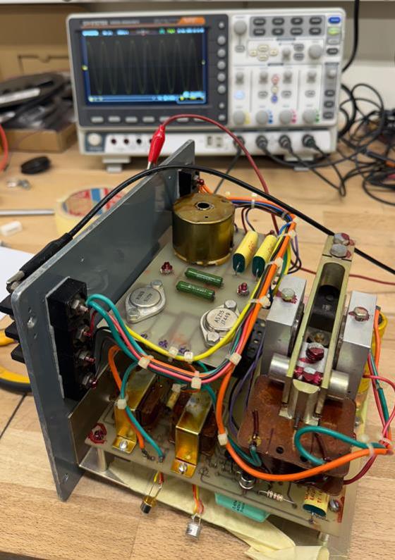
How the detection works
A wire net is stretched across the slope above the railway. The station electronics send a monitoring signal through a transformer pair into the net and measure it all the time. When a rockfall or landslide tears the net, the signal stops, and the system raises an alarm for the traffic office and switches on the warning lamps along the track.
The same electronics also detect faults in the net, such as a breakdown of the insulation, so that a failing net is reported as a fault and is not mistaken for an alarm.
The problem we solve
These systems have worked for decades, and they are safety critical. The parts are no longer made, there are no spare transmitters, and when one fails the traffic on the section is disturbed.
We keep them running. We renew the electronics, repair what was thought to be unrepairable, diagnose the whole system and not just the box, and leave behind documentation and procedures so that the maintainers can look after it themselves.
The principle in motion
Simplified diagram. In the real system the alarm is delayed by a few seconds so that short disturbances do not trigger it.
Renewed detection electronics, northern Primorska
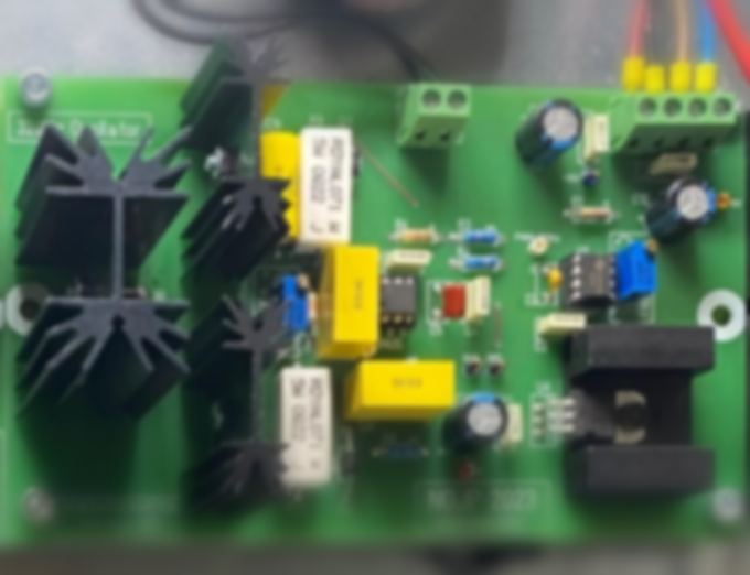
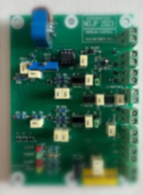
On a slope above the railway at Nova Gorica, an old detection system needed new life. In 2023 we renewed its electronics: a generator card and a measuring card. Components that were no longer on the market were replaced with functional substitutes, and the detection and signalling concept stayed exactly as before, so the operators work as they always did.
The generator card produces a clean 320 Hz sine wave with adjustable frequency and amplitude. The measuring card measures in a galvanically isolated loop and has two adjustable limits, one for a cut net and one for a faulty net. It also keeps the alarm until it is reset, even if the fault disappears.
The alarm is delayed by 3 to 4 seconds, which filters out short disturbances caused by heavy downpours and lightning. When it triggers, the warning lamps along the track light up, a red lamp and a buzzer start in the traffic office, and an event counter goes up by one. A separate orange lamp reports faults, such as a lamp supply failure or a breakdown of the cable insulation.
We delivered the cards with maintenance instructions, a step-by-step procedure for setting the limits and a logbook for the maintainers. In field tests, a cut at either fuse and a cut in the middle of the net were all detected.
Five days to repair a 1960s transmitter, Zasavje
On a Friday in November 2025 a transmitter of the detection system in Zasavje failed. The maintainers had no spare and traffic on the section was badly disturbed. By 3 pm we were collecting the faulty transmitters, and they went straight to our electronics lab.
The transmitter is built around a resonant tuning fork and three stages of germanium transistors, a technology from the 1960s. The fork must be tuned very precisely, and every stage must be set symmetrically. Because the fork vibrates all the time, the circuit boards and the stiff copper wires inside had suffered over the years.
Replacing the failed transistor was not enough: the output was 40 percent too low and its shape was distorted. Spectral analysis showed the real cause in the primary oscillator, where sharp voltage spikes were killing the sensitive transistors. We measured the 3D magnetic flux around the fork with a magnetic field meter and a 3D magnetic sensor, and tuned the fork and the coils until the spikes were gone.
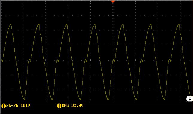
We also replaced all the rigid copper wires and the solder on the power parts. The repaired transmitter delivered a clean sine wave of 50.8 V rms on open terminals, inside the required 40 to 55 V. It was installed on the track on 26 November 2025.
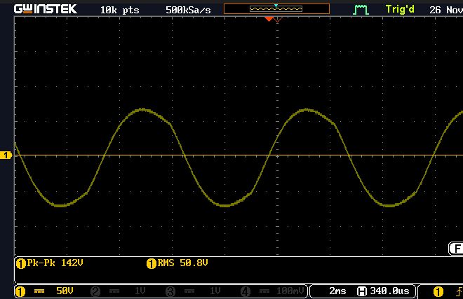
We also found that the start-up time is a simple health check that needs no opening of the device: a good transmitter builds up its output in about 2 seconds, a poor one can need tens of seconds. We assess every transmitter first, because the success of a repair depends on the condition of its components.
Diagnosing the whole system
When a detection system stopped noticing a simulated cut after several days of rain, we did not stop at the electronics. We studied the old and new documentation, tested the device on the slope and measured the currents in the loop. The electronics were fine, and the weather dependent fault was in the net itself: parasitic current paths where the conductor touched grounded posts and wet vegetation.
The result was a clear list of actions for the maintainers, and a proposal to upgrade the electronics so that they can also detect an increase of the current in the loop and report insulation problems automatically.
Maintainable by design
For every system we write down how it works, how to set it up and what can go wrong, and we teach a procedure for adjusting the limits that a maintainer can follow with a multimeter. Faults are sorted into mechanical and electromagnetic ones, and every service intervention is recorded.
For repaired transmitters we add serial numbers and a record of measurements and repairs, protect the components with at least two layers of lacquer and check the output once more after closing the case.
What the customer gets
Protection stays on
The proven detection concept is kept, so the line stays protected without replacing the entire system.
Parts that are no longer made
Unavailable components are replaced with functional substitutes, and even 1960s electronics can be repaired.
Fast reaction
From the call to a repaired transmitter back on the track in five days.
Fewer false alarms
A short alarm delay filters out disturbances from storms and lightning, and faults are reported separately from alarms.
Documented and traceable
Instructions, calibration procedures, logbooks and serial numbers for every unit.
Whole-system view
We look at the generator, the cables, the transformers and the net together, and we find the real cause.