
Case studies / Camshaft sensor tester
Camshaft sensor tester: every test in 10 seconds
An end-of-line tester for an automotive camshaft timing sensor, built for an industrial partner. It contacts the part once, measures resistance, capacitance and inductance, then spins a magnet in front of the sensor and checks the signals, their 100 ns edges and the exact switching angles.
Talk to the founder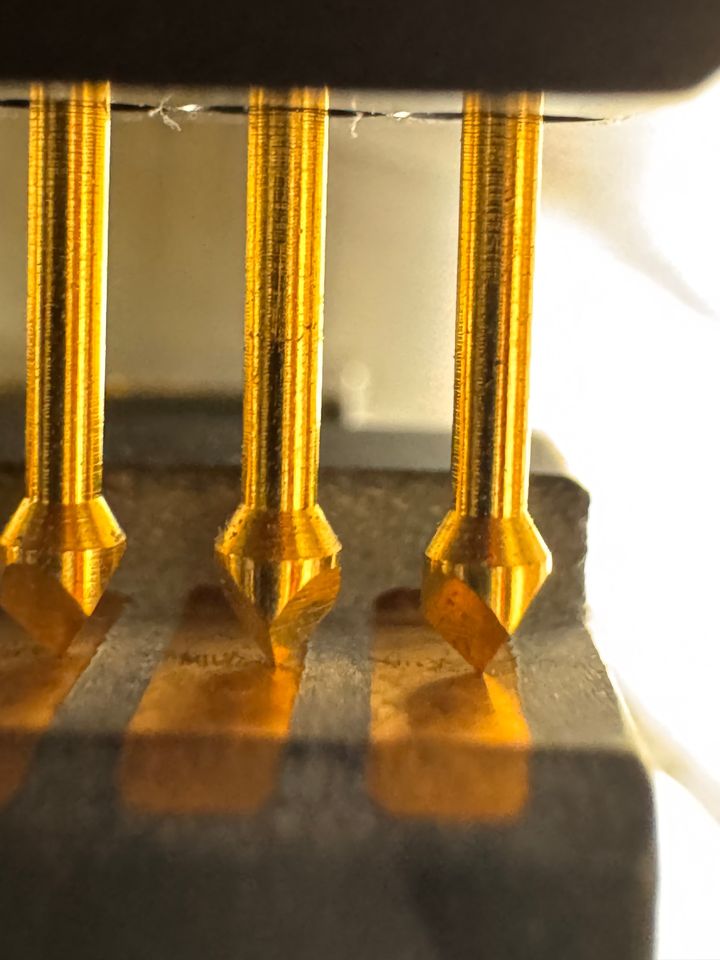
The challenge
The sensor sits in the cylinder head of a passenger car and reads the position of a magnet with several Hall switches, for variable camshaft timing. A bad sensor means a bad engine, so every single part is tested.
The production line asked for a cycle time below 40 seconds per piece, running in three shifts, seven days a week. The test therefore had to take only a small part of that time, and the probes had to touch the milled contacts of the sensor without damaging them.
Our solution
Normally an in-circuit test and a functional test are two stations. Here they are so fast that we merged them into one: the part is contacted once, and everything electrical is done in about 10 seconds.
The tests run on a compact National Instruments PXI system that we configured and program ourselves in LabVIEW, together with a high-precision SICK encoder for the angle of the magnet.
What happens in 10 seconds
- 1. Contact
Spring-loaded probes touch the contacts of the sensor. Relay multiplexers route each pin to the right instrument, so one contact serves every measurement.
- 2. Scan and check
The 2D DataMatrix code of the part is scanned and checked in the server and ERP system, to confirm that this part is allowed to be tested.
- 3. In-circuit test, about 3 s
The impedance between every combination of pins, and at the end the capacitors in the part. This shows open contacts, shorts and damaged parts before the real functional test begins.
- 4. Functional test, about 7 s
The sensor is powered and a magnet rotates in front of it, the way the camshaft moves in the engine. We measure the current consumption, the voltage levels, the rise and fall times of the edges (around 100 ns), the switching points and the temperature.
- 5. Switching points
For every output we measure the angle at which it switches. The encoder gives the position, and hardware triggers inside the PXI system tie each edge to that position.
- 6. Data
The results are processed, stored locally and sent to the server, the ignition and the ERP system.
- In parallel: temperature watch
All the time the system monitors the temperatures and checks that the temperature gradient is as expected. If it goes out of bounds, the test is aborted.
The station and its screen
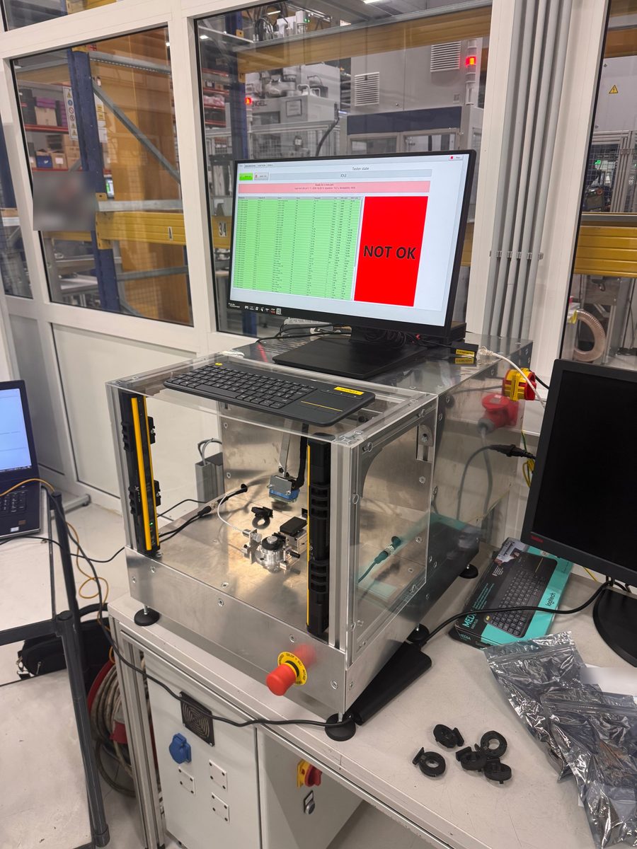
The tester is a compact bench-top station. The part sits in a fixture under a transparent cover, where the probes and the rotating magnet are. Safety light curtains and an emergency stop protect the operator.
The operator works on a large screen. Every measurement appears in the results table with its limits and its result, so a failing part is obvious at a glance.
The clip below is a real run at normal speed. The results table fills with the in-circuit measurements within a few seconds, and the functional tests follow straight after.
Fast edges, measured properly
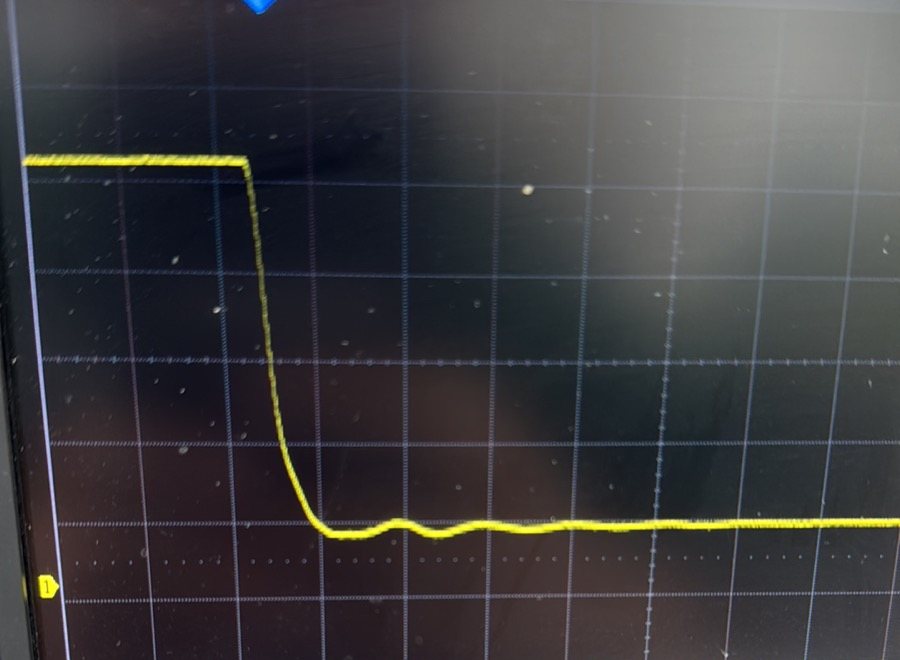
The outputs of the sensor switch in around 100 nanoseconds. To measure that, the oscilloscope samples one billion times per second, which puts about a hundred samples on a single edge.
Switching positions are the hardest part. Each edge is timed against the angle from a high-precision SICK encoder (40,000 positions per revolution) in hardware, using the advanced triggering of the PXI platform, so the result does not depend on how fast the software happens to run.
Recipes and roles
The software uses configurable recipes, so the limits and the test sequence are set by parameters and not by programming. Recipes can be changed only by an administrator.
The same software runs a new product variant by loading another recipe.
Operator and administrator
A regular operator can only run the test. The options for diagnostics and recipe settings are not available to the operator.
The administrator adds new operators with their passwords and runs the system health checks and diagnostics.
The instruments behind it
We do not only use high-performance instruments, we know how to get the most out of them: the speed, the timing and the accuracy that current technology allows.
- PXIe-1083 chassis5 hybrid slots, Thunderbolt 3
The backbone of the tester, up to 2 GB/s per slot, with a laptop or an industrial PC as the controller.
- PXIe-4082 multimeter6½ digits, with L and C
Resistance, capacitance, inductance and voltage levels with a single precise instrument.
- PXIe-5110 oscilloscope100 MHz, 1 GS/s, 2 channels
Captures the 100 ns edges and the switching of the outputs, with a 64 MB memory.
- PXIe-6612 counter/timer8 channels
Precise counting and timing of the encoder and trigger signals.
- PXI-2503 multiplexers2 modules, 24 channels each
Relay switching that routes every pin to the right instrument, so one contact serves all tests.
- SICK DFS60B encoderDFS60B-BDMA10000, 40,000 positions per turn
10,000 pulses per revolution, read with x4 evaluation: a step of just 0.009°. It tells us the exact position of the magnet when each output switches.
Shielded connection blocks and cables keep the fast signals clean.
What the customer gets
One station, one contact
In-circuit and functional tests merged, with no extra handling between them.
Plenty of time left
About 10 seconds of testing in a cycle that was allowed to be up to 40.
Precise measurements
Edges around 100 ns and switching angles tied to a high-resolution encoder.
Gentle on the part
Spring probes touch the milled contacts of the sensor.
Traceable results
Every part is checked in the ERP system before the test, and the results are stored locally and sent to the server afterwards.
Recipe driven
A new product variant needs a new recipe, not new programming.
Safe to operate
Operators can only run tests, while recipes and diagnostics stay with the administrator.
Built for the line
Designed for three shifts, seven days a week.