
Case studies / Marshalling yard control system
Marshalling yard control system, Ljubljana Zalog
A complete replacement of the computer control system of Slovenia’s central marshalling yard, built on real-time controllers and FPGA circuits, with hot-swap redundancy for every vital function.
Talk to the founder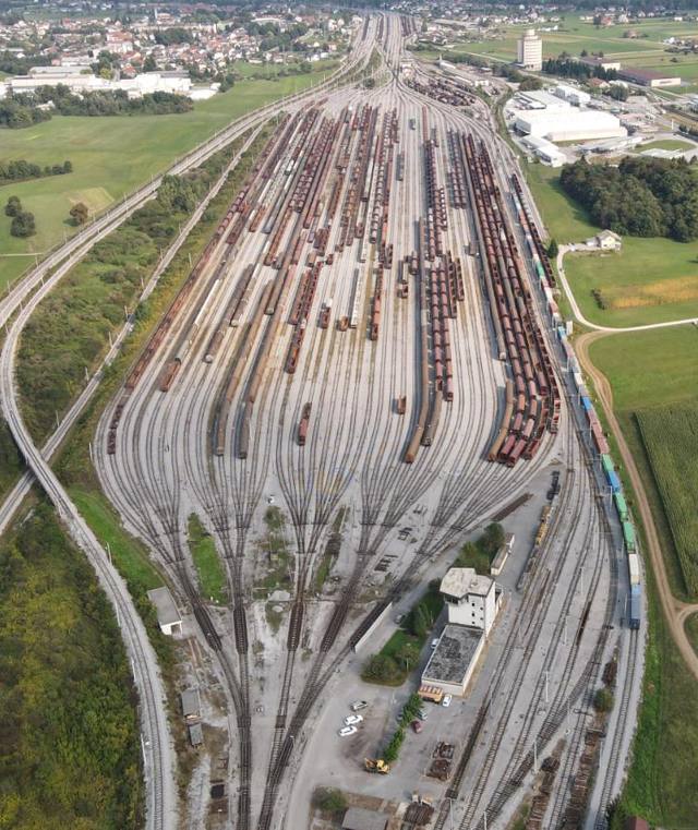
The challenge
The marshalling yard in Ljubljana Zalog sorts freight wagons by letting them roll over a hump. Its computer system sets the switches, controls the track brakes and measures how much free length each classification track has. The existing system had to be replaced, and the yard could not stop.
The requirements were strict: the same operating procedures for the operators, the same performance and braking accuracy, and no changes to the basic safety of the installation. All field equipment stayed in place: switch drives, track circuits, track contacts, speed radars, hydraulic power unit and the track brakes themselves.
Our solution
We replaced the computer system with 13 industrial real-time controllers with FPGA units, programmed in LabVIEW. They are spread over four locations: the computer room, the main command post, the hump and the hydraulic station. Copper links connect the command post (as a redundant pair, switchable by the operator), and optical fibre links the hump and the hydraulic station.
The new system first ran in parallel with the old one, connected to the same field signals through high-impedance inputs, so it could be checked against live traffic before taking over.
System architecture
Simplified diagram. Switches, track brakes and free-length measurement each run as a pair of controller sets. A master controller supervises everything and performs the hot-swap.
Real-time control on FPGA
Time-critical logic runs on FPGA circuits, and the heavy arithmetic runs on the real-time processor. Each switch has its own control circuit inside the FPGA, with axle counting and a debounce stage that filters false counts from bouncing signals and logs the transients to help maintenance find faults.
Because the vital functions live in the FPGA, they do not depend on how busy the processor is. The control, monitoring and storage functions run at 20,000 cycles per second, and digital inputs are sampled at 140 kHz.
Hot-swap redundancy
The master controller checks every I/O module, every controller, every FPGA and every program loop in the system. On a critical fault it switches to the redundant set immediately by switching the power of the output modules, and informs all workstations. A fault in a function without redundancy is reported at once and, if a safety function is affected, automatic operation is stopped.
The hot-swap is tested by causing faults on purpose, for example by disconnecting an I/O module while the system is running.
Safety checks and sensor redundancy
The system checks itself and the field all the time, and it is built so that the loss of one sensor does not stop the yard. Every track contact is monitored on all possible routes, not only on the route that is set. Because the system knows how many axles each convoy has, it knows how many axles every contact must count.
If several contacts count the same wrong number, the convoy has taken a wrong route. If only one contact disagrees, the fault is reported without affecting the operation, and the other sensors cover the lost sensing. A contact that keeps failing is taken out of service and the next contact takes over its function.
If two consecutive contacts fail, convoy tracking is no longer possible and the switch automation is switched off safely. A route is never set for a second convoy while the previous one is still in the switch area, and runaway convoys are reported to the operators.
The braking system follows the same philosophy: if a collision of convoys inside the track brake is possible, it deactivates the brake so that the collision happens outside the most expensive piece of equipment in the yard.
Track brakes that think ahead
The brake controller measures how each wagon accelerates down the hump and classifies it as a good, medium or bad runner. The operator then chooses the exit speed, and the system regulates the hydraulic brake to reach it. Manual commands always have priority over the automatic control.
A dedicated FPGA circuit measures the wagon’s travel time over the known distance with an accuracy better than 500 ns. The signal of the original radars is processed in the FPGA as well: each pulse is 6.21 mm of travel, and the circuit doubles the resolution to 3.105 mm. The braking logic recalculates at 20 kHz and opens one half of the brake early to bring the speed close to the target, compensating for the delay of the hydraulics.
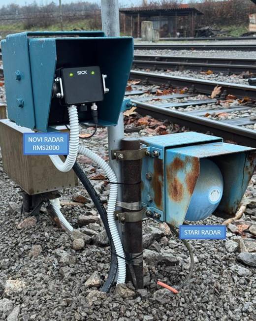
On some brakes we now use a new digital radar instead: a true 2D radar scanner, connected to the computer room over optical fibre, which gives us advanced measurement of the passing wagons.
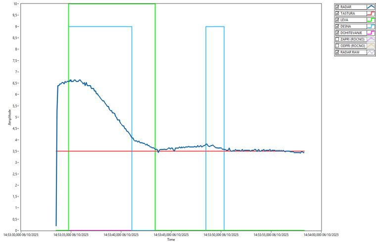
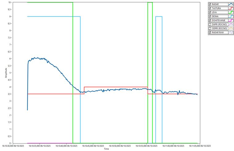
In 2025 we upgraded the braking algorithm so that the brake closes before the wagons enter it, instead of about a second after braking starts. The charts show the same brake before and after the upgrade, measured with our dataloggers. The brake is loaded less, and the chance of light wagons lifting up in the brake is reduced, which lowers the risk of derailment on the most expensive piece of equipment in the yard.
The upgrade was validated on all five track brakes with a locomotive-and-wagon test, observed from a safe distance.
Kept up to date
- Project start, 2019–2020
The project starts with the replacement of the complete computer control system. The old and new systems run in parallel on live traffic before the changeover.
- New wheel sensors, 2023
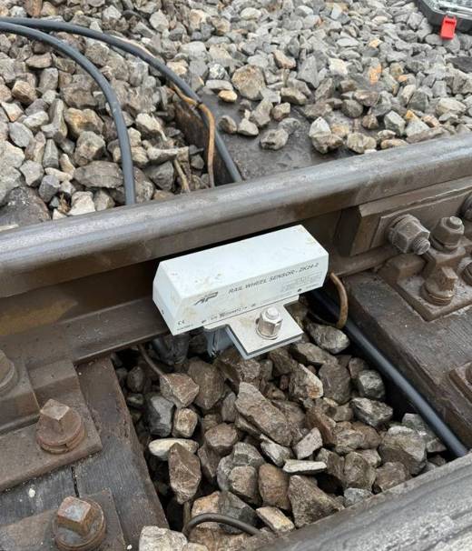
Failing old track pedals are replaced with Altpro ZK24-2 sensors. In field tests every axle of locomotives and wagons was detected, and the system carried out three automatic sorting runs.
- New speed radar, 2024
The original radars were no longer available. We developed adaptation electronics for the SICK RMS2000 and compared both radars on a live braking: the signals had the same shape, with no measurable delay. On some brakes we now run a new digital radar, linked to the computer room by optical fibre.
- Smarter braking, 2025
The new braking algorithm is validated on all five track brakes. A review of 226 convoys on one brake found no radar problems.
- New hydraulic power unit, 2026
The new hydraulic power unit, developed in collaboration with Oprema Ravne, gets a matching control and SCADA, with two independent control paths: the relay system and the controller system over optical fibre. The operator chooses which one to use.
New hydraulic power unit and SCADA
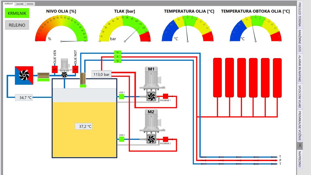
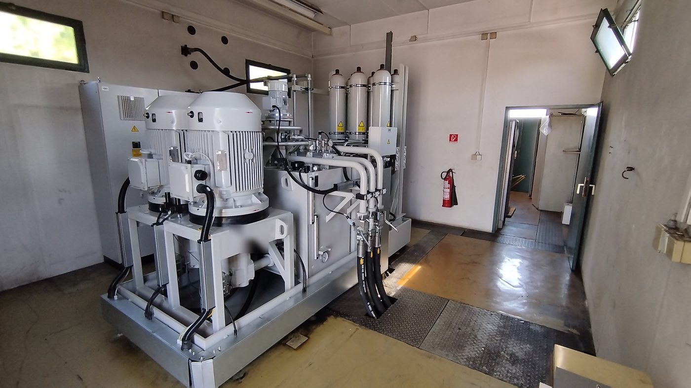
The yard’s hydraulic power unit was replaced with a new one, developed in collaboration with Oprema Ravne. It works the same way and gives the same performance as the old one, but it can now be controlled in two independent ways: through the relay system or through the new controller system over optical fibre. The operator chooses at the control desk which one to use.
The new SCADA screen shows the oil level, pressure, oil and winding temperatures, both pumps, the filters and the accumulators. Its controls and indicators copy the shape and colours of the physical buttons on the desk, so operators recognise them immediately.
Before the unit runs in automatic mode, the system checks the critical conditions, such as oil level, pump and motor protections, fuses, supply, pressure, temperature, line controls and valve positions. If one is lost, the unit stops at once. Less serious conditions, such as a clogged filter, are shown as warnings.
Custom interface electronics
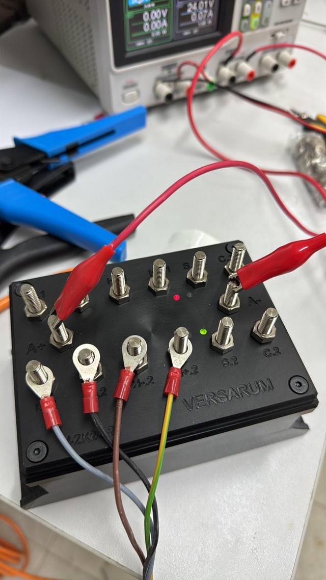
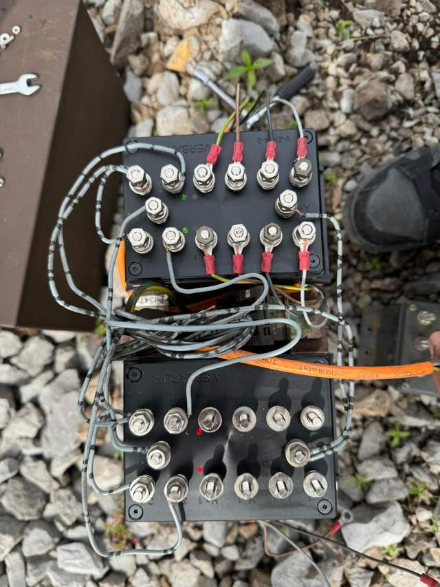
Between the new controllers and the existing field equipment we built our own interface electronics. They let the new system connect in parallel with the old one through high-impedance inputs, without disturbing it, so every function could be checked on live traffic before the changeover.
The same approach lets us connect modern sensors and radars to equipment that was designed decades ago. For the new radar we developed adaptation electronics that take the power from the relay room and send the measurements over the network. For the Altpro ZK24-2 wheel sensors we built our own interface modules that connect them to the yard’s existing inputs. This is why existing cabinets, cables and field devices could be kept.
What the customer gets
Higher availability
Hot-swap between redundant controller sets keeps the yard working when a component fails.
No change for operators
The control desk and the working procedures stay the same, so the operators keep working as they always did.
Lower cost and risk
Existing field equipment, cabinets and cables are reused, and the old system is only switched off after the new one has proven itself in parallel operation.
Planned maintenance
Detailed monitoring of switch drives, brakes and track contacts makes it possible to predict maintenance work.
Diagnostics and simulation
A maintenance workstation can simulate field signals and inspect every track contact, switch drive, track circuit, brake and radar.
Long-term support
LabVIEW code compiles for newer controllers, so the system can follow hardware generations. Operating data is stored for at least a year and can be exported.